Making sustainability tangible by developing projects that unlock the untapped energy and environmental potential of organic feedstock.
SusBDe initiates projects through local partnerships, securing land and permits, and ensuring smooth integration with stakeholders. Custom designs by local EPCM and tech partners enable coordinated execution. We oversee commissioning, offering continuous performance monitoring and recommendations for optimal efficiency and reliability.
The vision of our Founder Mr. Bert Jägel is still part of our DNA which has a strong focus on contributing to society by having an impact via developing sustainability projects.
SusBDe has projects in construction and development in India, Senegal, Poland and Morocco.

The projects we deliver are supported by the relevant stakeholders.
Working together with our partner organizations, we ensures that all important aspects are included in the feasibility assessments.
Our projects are ready to be engineered, built and taken into operation with necessary permits by our partner organizations.


Our Dutch-based development and coordination platform, overseeing project execution, technological partnerships, and structured financing.
CIN 87252023
Our Cyprus based company managing core technology rights, royalty frameworks, and insurance-backed project structures.
CIN HE 459644
Our specialized entity focusing on monetizing environmental performance through high-integrity carbon credits under leading global verification standards from Cyprus.
CIN HE 459645
Together, these entities form the operational and strategic backbone of the SusBDe Group. From project origination to risk mitigation and carbon monetization, we offer an integrated approach designed to align economic and environmental returns. Our group structure ensures transparency, scalability, and investor-grade governance across all project phases.
Explore the sections below to learn more about each entity’s function and its contribution to the SusBDe mission: building bankable infrastructure that drives climate-positive impact and long-term value creation.


Our proven and bankable anaerobic digestion concept minimizes CHG emissions and water consumption.
Since the early 2000s, we've developed over 100 biogas plants worldwide in close cooperation with partners.
Our project team has over 60 years of combined experience and a track record of delivering industrial and renewable projects globally. SusBDe and partners operate over 100 plants, covering everything from conceptual development to operations and maintenance. We handle biogas projects end-to-end, from feedstock pre-treatment to supplying pure CBG to the local grid.

Through our structured and methodical modular project development approach, SusBDe has not only created a viable project solution but has also ensured that the financial results are covered by insurance.

Pre digestion treatment of organic matter.
Formation of biogas from organic matter.
Creation of fuel-grade methane.
Transferring the generated Bio-CNG or Electricity to the Distribution grid.
Biogas is produced from poultry manure through anaerobic digestion, where microorganisms decompose organic matter in the absence of oxygen.
Primary Composition: CH4 – 50-70%; CO2 – 30-50%
Impurities like Nitrogen, CO2, H2S, and moisture are removed to increase the methane content from generated Biogas. This purified biogas is compressed to produce CBG.
Generation of Biogas creates streams of additional off-takes, like Liquid Fertilizer (Liquid Digestate) and Compost (Solid Digestate).
The development of a project is divided into:
The Development Phase involves planning, securing approvals and attaining financial feasibility. It includes the evolution of design from concept to detail to set the stage for the commencement of Project Execution.
The Construction Phase is the execution stage where the project is built. It includes material procurement, resource mobilization, and construction monitoring, ensuring adherence to standards, timelines, and budgets.
The Operation Phase focuses on maintenance and management. It ensures optimal performance through monitoring and necessary optimization, for long-term success.
This technical reader details SusBDe’s advanced anaerobic digestion system for high-solids poultry litter. Designed for 35 million m³ of annual biogas output, the facility processes chicken broiler and layer litter, DAF sludge, and recycled process water. Key features include high-efficiency mixing, dual-phase thermophilic digestion, and integrated nutrient recovery. Post-digestion, the system separates and valorizes digestate solids as organic fertilizer, while ammonia is captured and converted into ammonium sulfate. CO₂ is also recovered for commercial use, ensuring maximum resource recovery.
This technology reader represents a facility of around 35 Million m3 of biogas annually, a cutting-edgesolution for the sustainable treatment of chicken litter and organic waste. Trucked-in feedstocks—including chicken litter, fat, grease, and process water—are collected and stored in dedicated bunkers and tanks.Prior to digestion, all materials are homogenized to ensure consistency.
The core of the process is a temperature-controlled anaerobic digestion system that utilizes a two-step approach: pre-digesters initiate organic breakdown, while main digesters focus on methanogenesis to optimize biogas production. The resulting raw biogas is then upgraded via advanced membrane separation into high-quality renewable natural gas (RNG). Post-digestion, the material is separated into solid and liquid fractions. The solid digestate is used as anorganic fertilizer. The liquid portion undergoes ammonia stripping, recovering nitrogen in the form of ammonium sulfate—a concentrated and valuable fertilizer product.
This integrated facility demonstrates the future of circular, low-emission energy and nutrient recovery. A detailed video on the process flow can be seen here.
Poultry litter, a mixture of manure, bedding material, feathers, and spilled feed, is a nutrient-rich organic byproduct generated in large quantities by the poultry industry. While traditionally used as a fertilizer, unmanaged disposal of poultry litter can lead to significant environmental concerns such as odor, nutrient runoff, and ammonia emissions. However, due to its high organic content and relatively consistent availability, poultry litter presents a strong potential for energy recovery through anaerobic digestion (AD).
This document outlines the technical specifications and operational design of a facility developed for the anaerobic digestion of poultry litter and organic waste streams. The plant is designed to receive, process, and convert high-solids poultry litter—sourced from broiler and layer farms—along with liquid feedstocks such as DAF (Dissolved Air Flotation) sludge and recycled process water, into renewable energy and nutrient-rich fertilizers.
The core objective of the facility is to transform organic waste into valuable resources through a controlled anaerobic digestion process. The resulting biogas is upgraded to renewable natural gas (RNG), while the digestate is separated into solid and liquid fractions for further recovery. The solids are utilized as organic fertilizer, and the liquid fraction undergoes ammonia stripping to recover nitrogen in the form of ammonium sulfate.
This facility represents a modern, sustainable approach to managing poultry waste while supporting circular economy goals. It incorporates robust feedstock handling systems, advanced mixing technologies, grit management strategies, and downstream biogas purification and nutrient recovery processes. The following sections describe each system component in detail, highlighting their function, capacity, and integration within the overall process flow.
This section outlines the procedures and systems for receiving, handling, storing, and preparing feedstocks prior to anaerobic digestion. The primary solid feedstock—poultry litter—is collected from local broiler and layer poultry farms, while the primary liquid feedstock is DAF (Dissolved Air Flotation) sludge generated from poultry processing facilities. All feedstocks are processed and homogenized to ensure consistent slurry quality for optimal digester performance. Supporting systems include water addition, recycled liquid integration, and storage infrastructure designed for operational efficiency and emissions control.
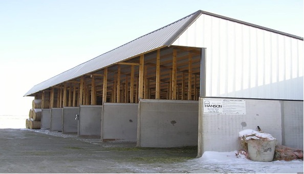
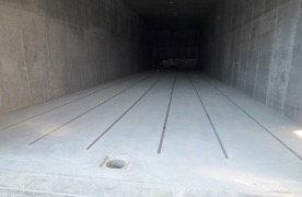
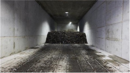
The litter is received into underground bins and peristaltic pumps forward the litter to a distribution conveyor into the storage bunkers. The bunkers can get wetted to form a crust over the litter to reduce ammonia emissions into the air. From the bunkers, the litter is moved by skid steer as needed to smaller underground bins where a screw conveyor picks up the litter and feeds peristaltic pumps, to pump the litter into the mixing tanks. Water is added to the litter with spray nozzles in the conveyor compartment to increase the efficiency of pumping the litter / water slurry to the mixing tanks. The DAF sludge and recycled centrate from the ammonia recovery system is added to the mix tank. The mixers in tank stir the slurry mixture to ensure a homogenous slurry mixture for feeding the digesters.
Feedstock for the anaerobic digestion facility includes poultry litter sourced from broiler and layer chicken farms, as well as DAF sludge collected from poultry processing operations. The poultry litter has high solids content, while the DAF sludge serves as a nutrient-rich liquid component. Both materials are combined and processed into a uniform slurry that can be efficiently pumped and digested.
Grit Removal
Grit present in the layer litter can either be kept in suspension and allowed to pass through the anaerobic digestion process—where it would be removed along with the digestate solids post-digestion—or it may be removed earlier, either at the time of litter reception or after storage and before being fed to the digesters. Each option presents its own set of advantages, disadvantages, and cost implications, all of which must be carefully evaluated. The currently preferred approach is to remove grit using settling tanks and screens after digestion and prior to the separation of digestate solids.
The primary solids to be received are chicken broiler litter at 85.9% total solids and chicken layer litter at 75.5%. Each shall be received by way of 20 – 25 ton back dump trucks 5 days a week 8 hours of each 9-hour shift. The receiving area will accommodate two trucks at a time and each truck will be unloaded within 20 – 25 minutes allowing for receiving three to four trucks per hour.
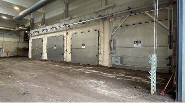
The litter will be received into two underground bins with motor-controlled covers, each with a capacity of 40 tons. The truck will back up a ground level hopper chute and activate the motor control to open the bin cover. Once the cover is open, the truck will back-dump its load into the hopper chute, which directs the litter into the below-ground bin. After the truck is emptied, the driver will activate the closing of the bin cover and, once closed, will pull away to make room for the next truck.
The broiler and layer litter will be unloaded into separate underground bins sized with a capacity of 40 tons each (minimum broiler litter bin size 54 m3 and 77 m3 for layer litter).The average truck load will be about 20 to 25 tons but will vary between 15 and 27 tons in each load with a total of 15 -16 trucks per day required to deliver all the litter.
The bins are equipped with water spray nozzles to allow moisturizing each load of litter with about 10 tons of water per load.The bottom of the bin is equipped with a screw conveyor that will move the mixture to the suction side of peristaltic pump which will pump the litter to a distribution conveyor system above the storage bunkers.
Storage of the litter in the bunkers sized for 14 days of storage of each type of litter. Each bunker can hold about 884 m3 of litter, with 6 bunkers used for storage of broiler litter and 4 for layer litter. A total of 10 bunkers will be constructed.
The bunkers will be covered with a building structure that has natural ventilation. The bunkers will have water sprayers to wet the litter with fresh water to crust the top of the storage pile and prevent excess ammonia vapors escaping into the atmosphere.
The bunkers will be filled from the bins using a distribution conveyor in each bunker, to allow for even distribution of litter within the bunker.
DAF sludge is received by way of twenty-four or more, 23 liter tanker trucks per day for 5 days a week. The tanker truck unloading accommodats at least 2 trucks simultaneously and each truck can be unloaded within 25 minutes of arrival at the unloading station such that 4 trucks per hour can be received and unloaded. The DAF sludge will be stored in 3 tanks with a minimum total capacity of 14 days of storage time. The total storage required is 5195 m3, 1732 m3/tank (about 1.7 million liters per tank).
From the DAF tanks, the DAF slurry will be pumped to the mixing tank.
The litter bunkers will be unloaded with a bucket loader with the litter dropped into the hatch of a covered underground bin with a capacity of 11.3 m3 each, two bins total. Each bin will be equipped with a screw conveyor and water spray nozzles with water added as the litter is conveyed to a peristaltic pump. The litter and water slurry mix will be pumped to the mixing tanks.
There will be two mixing tanks sized for one day of mixing the chicken litter, DAF sludges, recycled water, and fresh water to achieve a homogenous mix of the feedstocks.
Mixing of the slurry in the tanks will be accomplished with external pumps recirculating the slurry mix with the suction of the pumps drawing from the bottom of the tank and returned through several piped connections along the outside of tanks creating a continuous horizontal and vertical stirring action of the mixture in the tanks.
The two mix tanks combine have a capacity for one day of storage plus 5% additional unfilled headspace, approximately 1 million liters each. The feedstock slurry will be pumped to the AD Hydrolysis Tanks using three pumps total each sized at 50% of the total pumping required, approximate flow rate of 742 lpm for each pump.
The DAF sludge stored in the DAF tanks will be pumped to the mixing tanks at a rate of flow totaling about 246 lpm by three pumps sized to pump at least 265 lpm each, in other words 3 x 50% each sized pumps.
Recycled water from the ammonia recovery system will be pumped into the mixing tank at a rate of approximately 680 lpm (40.54 m3/hour) to add moisture to the chicken litter slurry and DAF sludge mixture.
The anaerobic digestion facility is designed to process a feed slurry with a daily input capacity of approximately 2,005.75 tons per day (tpd), equivalent to 1,823.4 metric tons per day (mtpd). This corresponds to a total volume of 2,032.4 cubic meters of slurry handled each day. The feed slurry is characterized by a dry matter/total solids (DM/TS) content of 16.86%, indicating a relatively high solids concentration suitable for high-solids digestion processes. The total nitrogen content of the feedstock is approximately 0.42% of the dry matter, which provides a balanced nutrient profile conducive to stable anaerobic digestion and efficient biogas production. These parameters define the input requirements necessary to maintain optimal operational performance of the biogas plant.
Hydrolysis is the first step in the anaerobic digestion of organic material. There are two hydrolysis tanks each sized for 5 days of HRT. Each tank is approximately 1,342,260 gallons (5081 m3) plus head space. The temperature of the feed slurry in the anaerobic digesters shall be maintained in the thermophilic temperature range of 122 - 131⁰F (50 to 55⁰C).Total HRT for thermophilic anaerobic digestion is 20 days including hydrolysis.
Each hydrolysis tank will supply feedstock slurry to two digesters. Each of the digesters is sized for 15 days HRT, approximately 7,621.5 m3 each plus head space. The feedstock slurry in the digesters will be continuously stirred by way of a recirculation loop drawing from the top of the digester tank, heated to a temperature of at least 52⁰C (125.5⁰F) with an external heat exchanger and returned to the digester near the bottom of the tank.
Each digester is equipped with four recirculation loops with an estimated flow rate of approximately 1,500 m3/hour such that a total flow into and from the digester and heat exchangers is 6,000 m3/hour.
Temperature control of the digester slurry is provided by an external heat exchanger loop and gas fired hotwater boiler supplied with the digester auxiliary equipment.
The hydrolysis tanks will have a positive suction ventilation system to draw out any biogas produced and will be piped to a common header with the AD tanks.
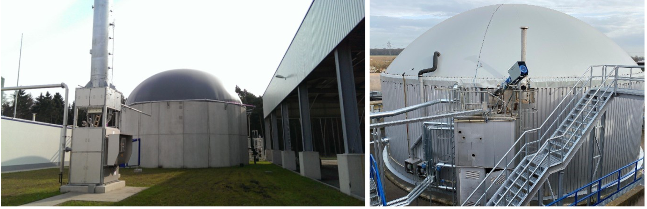
Each anaerobic digester shall be equipped with a double membrane roof and support structure that collects the biogas. The biogas outlet from the membrane roof of each digester is piped to a common header that includes the hydrolysis tanks vent lines. Two biogas blowers operating as part of the biogas treatment and upgrade system will maintain a low suction pressure drawing the biogas from the membrane roofs at a rate consistent with the amount produced.
Digester effluent (digestate) from the digesters using a common header pipe from the 4 digesters with two 100% sized pumps (alternating as needed) at a rate of approximately 66.25 m3/hour is pumped to the digestate buffer tank.
The digestate buffer tank will be a conical bottom tank used to settle grit to a screw conveyor for removal. The buffer tank provides for a continuous flow without upset to the digestate solids removal system and allows for any biogas trapped in the effluent time to percolate to the top of the buffer tank and be drawn out by a biogas blower to the biogas treatment system with the biogas collected from the digesters.
The digestate buffer tank shall is sized for a retention time of 30 minutes to allow grit to settle while the undigested solids and liquid is pumped to the digestate solids separation system by three pumps each sized at 50% flow.
The separated grit is processed through a screen that allows the water to be recycled while the grit is combined with the separated solids at the digestate solids cake dryer.
The digestate will be dewatered utilizing three decanter centrifuges operating in parallel at a rate of 22.1 m3/hour each. The solids will be dewatered to approximately 70% moisture. Polymers may be required to achieve separated solids of 70% moisture or less.
The solids from each centrifuge will be collected into a hopper and then transferred to a feed hopper for a rotary drum dryer by way of a screw conveyor. The hoppers and screw conveyor should be sized to handle 110 tons per day (100 metric tons per day) dry basis of solids transfer.
The liquid fraction (centrate) will be stored in a buffer tank sized to hold the total flow for at least for a 6-hour period (one quarter of the total flow for 1 day). The expected total liquid fraction flow rate is approximately 1343 m3/day. The buffer tank will be sized for at least 340.6 m3.
The digestate solids received at 35% dry matter and 65% moisture will be dried to 50% dry matter and 50% moisture using solar radiant heat. The digestate solid will be spread in layers in open drying rows and turned weekly to promote drying. When dried to 85% dry matter, the digestate solids will be collected by skid steer and loaded into a hopper for bulk loading or to a pelletizer that will compress and pelletize the digestate solids.
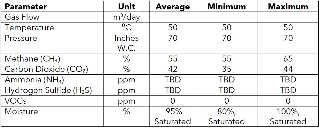
The raw biogas from the anaerobic digesters will be saturated with moisture and contain particulate matter, methane (CH4), carbon dioxide (CO2), hydrogen sulfide (H2S), oxygen (O2) and trace amounts of inert gases and volatile organic compounds (VOCs). The biogas treatment system is designed to remove moisture, particulate matter and H2S.
The expected total flow rate is approximately 100,487 m3/day. The biogas treatment system consists of two complete systems operating in parallel with a capability to clean 42.47 m3/min each, 84.95 m3/min of biogas total.
Each system will be designed such that media changes can be accomplished while the system is in operation. This will require lead-lag vessels. Media vessels may be shared between trains, for example the offline lag vessels can be valved as the lead vessels for either train as can each of the lead vessels when they become the lag vessel after a media changeout.
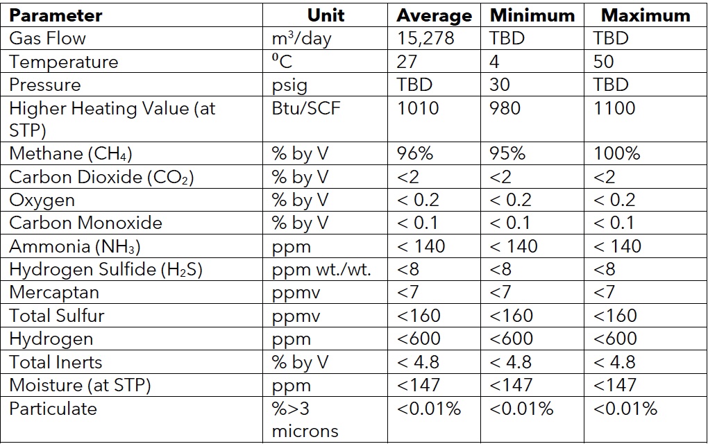
The cleaned biogas will be upgraded to pipeline quality renewable natural gas (RNG) with a membrane separation system that allows separation of the CO2 and the CH4.
The system shall be designed for a flow rate of approximately 55,560 m3/day and have an efficiency of at least 97.5% recovery of the biomethane with an option of 99% recovery.
The CO2 stream shall be recovered and chilled until it is in a liquid state to be stored for transport.An estimated 50,970 to 56,633 m3/day of CO2 should be recovered and processed intoapproximately 92 – 102 tons/day of liquid CO2.
The biogas to be treated approximates the parameters in the first table below and the final values will be determined by the design of the AD system and mass balance information. The second table gives the parameters of Treated Biogas for Pipeline Injection.
The liquid fraction from the digestate solids decanter stored in a buffer tank will be processed by minimum of four stripping systems (streets), each system to consist of 3 ammonia strippers and 1 CO2 stripper, total of atleast 12 ammonia strippers and 4 CO2 strippers. In each stripper air and liquid fraction are brought in close contact with each other. The liquid fraction is sprayed in at the top of each stripper using full-cone spray nozzles to maximize the contact area between liquid and gas. The spray nozzles will be selected to optimize droplet size, but still sufficiently large to avoid blockage. As such mass transfer area between liquid and gas will be maximized for fouling conditions. Air is introduced into each at the bottom via an air distribution system. The applied air flow rates will provide sufficient turbulence to maximize mass transfer in the system. Each stripper will be equipped with two pumps. One pump will provide internal circulation for spraying, while the other is used to feed the next stripper.
The goal of this stripper is to remove CO2 from liquid fraction, thereby increasing its pH, avoiding the need for caustic soda (NaOH) dosing every day. Fresh air is used as the stripping gas. The CO2 stripping is performed without additional heating since CO2 is more volatile than NH3. As such mostly CO2 is stripped. The CO2 stripper off-air is mixed up with the NH3 laden air from the NH3 strippers. The air mixture subsequently goes to the acid scrubber section for NH3 recovery.
Each street of CO2 strippers shall be capable of processing approximately 289 tpd (262.7 mtpd).
To strip ammonia, the liquid fraction will be heated to a temperature of 65°C (149°F). Each street will have heat exchangers on the feed to the first NH3 stripper to provide the required heat. 3 NH3 strippers are in place in each street. Liquid fraction will go through the system front to back, while air goes back to front. In each stripper the liquid fraction is contacted with air to maximize NH3 transfer from liquid to gas. This results in an NH3 laden air stream, and a liquid fraction stripped from NH3. The NH3 laden air stream is led to the scrubber section for NH3 recovery as ammonium sulfate, (NH4)2SO4. Scrubbed air is subsequently reused for stripping.
The influent ammonium concentration is around 3,526 mg N/L and the effluent concentration after stripping is 1,200 mg N/L. This means that 66% of the dissolved ammonium will be removed and recovered as (NH4)2SO4.
Each street includes a scrubber section for NH3 recovery. The gas stream resulting from combining the CO2 stripper exhaust and NH3 stripping exhaust is fed to the main scrubber, where the bulk of the NH3 is absorbed into the liquid acid phase. 70% w/w sulfuric acid (H2SO4) is used to maintain acid conditions. The exhaust gas of the main scrubber is then split. The main fraction is recycled to the NH3 strippers. The rest is purged through a small acid scrubber to prevent CO2 accumulation in the air recycle. The small scrubber is operated at low pH (<3) to minimize NH3 concentration in the purged air. The effluent ammonia concentration of the recirculated air is expected to be around 500 ppm. Purged air NH3 concentration remains below 15ppm.
Ammonia rich air is introduced at the bottom of the scrubber column while the sulfuric acid solution is sprayed at the top, creating a counter-current flow between the liquid and air. In addition, the scrubber is filled with packing material to optimize the contact area between liquid and water. In the scrubber an ammonium sulfate fertilizer is created, (NH4)2SO4. Water is added to the scrubber to obtain the desired fertilizer concentration (35% w/w) and compensate for volume losses due to evaporation. This is necessary to avoid ammonium sulphate crystallization in the scrubbers: above 35% w/w (NH4)2SO4 the probability of crystallization considerably increases potentially resulting in process disruption.
The system uses approximately 27.7 tpd (25.2 mtpd) of water and 13.4 tpd (12.2 mtpd) of acid to produce 36.2 tpd (32.9 mtpd) of fertilizer with 35% (NH4)SO4 and recover 3.7 tpd (2.44 mtpd) of ammonia nitrogen.


This document outlines SusBDe’s integrated technological approach to converting Municipal Solid Waste (MSW) into renewable energy. The proprietary process combines robust pre-treatment, high-efficiency anaerobic digestion, and advanced biogas upgrading into compressed biomethane (CBG). The system is designed for operational resilience, scalable deployment, and compliance with European and Indian environmental standards. The process architecture includes automated sorting, biological drying, digestate valorization, and ammonia recovery—enabling a true zero-waste solution.
The primary objective of anaerobic digestion is to convert the input feedstock materials into a morestable product. Segregation is the first and most critical step in the anaerobic digestion process, as itdetermines the efficiency and quality of the entire operation. When municipal solid waste reaches thefacility, it is a mixed stream of organic and inorganic materials. Through a combination of manual sorting and mechanical systems like trommel screens and magnetic separators, non-biodegradableitems such as plastics, metals, glass, and cardboard are removed. This ensures that only the cleanorganic fraction moves forward into the digestion process, where it is biologically broken down to produce biogas and nutrient-rich compost. Meanwhile, the recovered recyclables are collected separately and sent to appropriate recycling channels, where they are processed and reintroducedinto the supply chain. This careful separation enhances process efficiency, protects equipment,improves compost quality, and supports a circular economy by converting waste into both cleanenergy and reusable materials. The full process can be seen in detail in the video linked here.
Anaerobic digestion (AD) is the series of processes to breakdown complex organic matter to biogas and CO2. It involves 4 stages, hydrolysis, acidogenesis, acetogenesis and methanogenesis. It is also described as biological oxidation of biodegradable waste by microbes under anaerobicconditions or in the absence of air. In the content below we will provide an overview of the process, technologies, methodologies in which the above-mentioned AD process is done.
The incoming unsorted waste will be heterogeneous in nature and have impurities. In order to have ahighly efficient AD process, these impurities need to removed and the feedstock needs to be homogenised. Pre-treatment processes and segregation processes will have to be carried out toachieve this. Mechanical and manual segregation of the waste will aid in separating unwanted impurities from the actual feedstock. Mechanical segregation starts with a grabber that puts thematerial into the hopper unloading the waste materials via conveyer belts to a hand pick station, wherehand pickers physically segregate waste, and secondly through a drum screen and a magnet in whichthe separated organic fraction goes via a conveyor belt towards the digestion garage boxes. There are electro mechanical controls installed to monitor the operations.
After the feedstock is pre-treated and segregated the organic waste fraction goes into the digestion process where the waste is treated, broken down into simpler compounds, which aids the microorganisms to break down the material further releasing methane and CO2. The technology adapted here is dry-fermentation.
Dry-fermentation has various benefits over wet-fermentation, few major benefits are lower energyand water requirements. The most important benefit is that the dry digestion can handle impuritieslike plastic or big items like coconuts etc. The released gas is called biogas, a combination ofmethane, CO2, and few traces of H2S. The biogas is then passed through purification system whereCO2, H2S and other impurities are removed, hence the output gas have higher concentration of methane. This gascan be used as an alternative source for existing conventional fuels like CNG and gasoline. Apartfrom biogas, the AD process also produces
bio-fertilizer via the system of windrow composting. Bio-fertilizer is high in fertilizer properties and can be a replacement or supplement for producing conventional fertilizers.
The technology adapted is Integrated Mechanical Biological Processing Technology (MBT)System, it is one of the most innovative MBT process for the treatment and utilisation of residualhousehold waste. This technology has been identified as Maximum Yield Technology (MYT) by Zweckverband Abfallbehandlung Kahlenberg (ZAK) Kahlenberg Waste Treatment Association.
The focus of MYT is on extracting the complete raw material and energy content from the municipalsolid waste. Although the characteristic properties of MSW vary on a regional and international level,the key components are always the same.
MYT innovative, perfectly synchronized multi-step process cascade gains the following four main components from the input MSW and extracts the maximum potential from them while utilizing synergies for each treatment step most effectively.
Anaerobic digestion is a Dry Batch Fermentation Technology where in the organic fraction, including impurities such as silt and sand is fed into specially designed reactors. The anaerobe digestions system presents a dry batch digester, which is a static digester, in which the feedstock will not be pumped or moved; hence the feedstock cannot block any pipe, or other mechanical part; the amount of sand and silt in the fermentation tank is fully controlled because the feedstock will be only touchingthe garage boxes. The digester can take waste with an average dry solid content between 25-35% with no or less water addition.
Dry fermentation has advantages over wet fermentation, like
Dry anaerobic digestion is a modular system where every garbage box is an independent reactor.This provides very high reliability to the system because, should a failure occur to one of the units, the other garbage boxes can continue operating. Continuous operation is the key factor in a waste treatment plant where incoming waste flows cannot be stopped without major inconveniences.
Dry anaerobic digestion is also a very low operational cost system because the waste does not need any costly pre-treatment before entering the digesters. For the same reason, also maintenance is simple. OPEX are low also because the digestate does not require solid/liquid separation as it would occur when compared to a wet digestion system.
As soon as one of the Anaerobic Digestion (AD) garage-boxes is ready to be filled, the wheel loader retrieves the material from the temporary storage and feeds the garage-box.
Each AD garage-box consists of a sealed concrete structure equipped with a special door provided with a pressurised rubber seal. The concrete floor houses a series of parallel PVC pipes which arelengthwise incorporated in the floor. These pipes are provided with tapered plastic nozzles (spigots)and are connected via pneumatic valves to two high pressure blowers which are used for the following purposes:
Each garage-box outlet is then equipped with a series of pneumatic valves which are used for the following:
Please note that, based on the latest design, all the technological system is supplied on prefabricated and pre-tested SKIDs where all the equipment required for the process is installed. There will be a SKID dedicated to each AD garage-box, a central air/gas SKID, a central water system SKID, a central heating system SKID and a central compressed air SKID. It goes without saying that the SKID configuration minimizes the site assembly time and allows for most of the testing to be conducted already at workshop, before delivery.
The garage-boxes are also equipped with a sprinkling system which recirculates the liquid containedin the fermentation tanks. The sprinkling system is massively used in the beginning of the process to activate anaerobic process by inoculating the fresh material with the bacterial activity present in the fermentation tanks.
The fermentation tank and percolation perform multiple actions in the process:
In the AD garage-boxes, a slightly positive pressure (3-5 mbar) is maintained throughout the process to prevent air to enter the garage-boxes during the anaerobic phases. Each garage-box is also equipped with an over/under pressure protection valve which activates in case of excessive under/over-pressures and having outlet outside the building.
As soon as the material is fed to the AD garage-boxes and the door is closed the blower starts to recirculate the garage-box air through the spigot floor. This induces a preliminary aerobic processwhich rises the temperature quickly to the mesophilic (or if required Thermophilic) level required in the AD process.
Furthermore, the oxygen level in the air is dropping leading rapidly the process to anaerobic conditions.
After this first stage, the gas valve opens allowing the gas to be extracted from the garage-boxes. The gas is reaching the storage volume and mixes up with the gas coming from the other garage-boxes.During the process, the blower alternatively recirculates the gas through the spigot pipes in the material to optimize gas production and homogenize the process conditions in the whole batch of material.
At the end of the process, when the gas production lowers, the fresh air valve opens, and the blower starts to purge the garage-box from gas. Flushing is performed with air or, as explained in following section, in case of biogas upgrading flushing is with CO2. The gas mixture that is produced is firstutilized in the central gas system and when the methane concentration lowers below a certainthreshold the gas is stored in a “lean gas” additional holder. This is provided to maximize gas exploitation and minimize gas emissions during transient phases. The lean gas holder collects the gasmixtures which are not directly usable in the generators or upgrading systems but can be slowly introduced in the utilization during all phases where the methane concentration allows for that.
Subsequently, when the gas quality decreases even more, the lean gas is flared in a special flare. Support biogas is required when methane concentration drops below 10-15%. As soon as the gas quality is below the LEL (Lower Explosion Level) of methane, the exhaust gas mixture is further diluted with air coming from the halls and is then transferred to the biofilter.
When the analysing system indicates that the methane content in the garage-box atmosphere is below the LEL, the door safety interlock opens, and the garage-box can be opened. The material is retrieved from the AD garage-boxes with the wheel loader and transferred to the aerobic section.
The residence in the AD garage-boxes is set to 22 – 24 days. Experience shows that this retention time optimizes the gas productivity and leaves sufficient organic load to the material to be actively participating to the following aerobic process steps.
The biogas production and the methane concentration will vary along the whole process. A typicaldiagram is shown in the following screenshot (CH4 concentration indicated by red line):
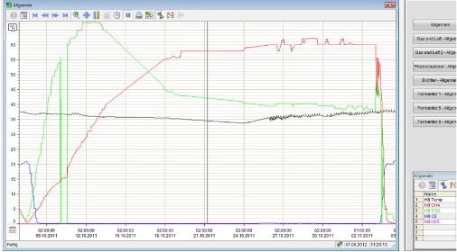
As it can be seen, methane concentration starts from “0” at the beginning of the process and returns to zero at the end.
The same cycle occurs in all the garage-boxes, however with a certain time lag depending on the garage-boxes filling schedule. This overlap of production will therefore induce a more constant diagram.
The biogas produced in all garage-boxes is flown to the gas holder and is here mixed with the gasproduced in the fermentation tank itself. The latter provides a constant contribution to the biogas production and methane concentration and guarantees that the CHP or the upgrading system is fed with the suitable gas quality.
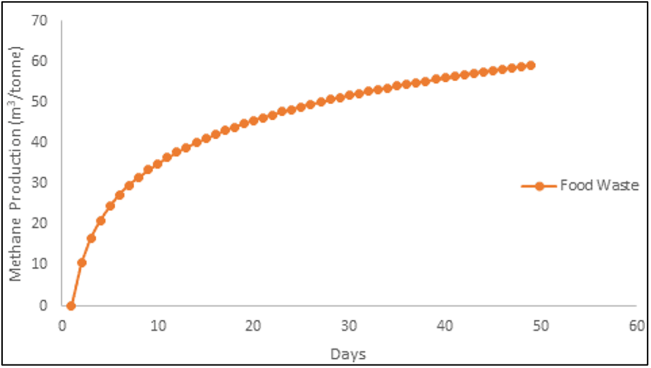
A typical cumulative methane production curve is shown in the following picture. This includes both the CH4 produced in the garage-boxes and in the fermentation tanks and shows that extending too much the process beyond 3 weeks is not meaningful.
The control system supplied consists of a computer that takes care of visualization. The computervisualizes the complete composting process. On the visualization, the operator can see the status ofthe installation, evaluate, and adjust process parameters, if needed. The computer monitors the composting process and is connected to a PLC that controls the process. The control parameters for the PLC are entered via the visualization.
The software in the PLC operates the process air and process water of all garage- boxes. Thecontrol software sets temperature, moisture level and oxygen level of the composting material to optimum conditions. However, only qualified personnel should operate the computer.
The parameter settings of the control software do not need to be changed after the composting installation has been started. The visualization is equipped with modem and communication software for quick support in case of problems.
The batch Dry AD process is a static one. This means that the material is not stirred or anywaymoved during the whole process duration. If on one hand, the absence of stirring limits the process efficiency, on the other hand this brings the big advantage of making the system very reliable, maintenance friendly and able to accept highly contaminated waste.
To compensate for the absence of stirring, the technology provides the feature of recirculating biogas during the process blowing it back through the spigot floor.
This provides the following benefits:
Gas recirculation is performed by the ATEX proof high pressure fan installed in the system.
In the system, the anaerobic process is inoculated via the liquid phase therefore avoiding materialrecirculation in the garage-boxes. The system is provided with a large fermentation tank where all thepercolate is directed. There is water level management system in fermenters to monitor the waterlevel and recirculation in the fermentation tank. The fermenting liquid is recirculated to the anaerobic garage-boxes most of all in the beginning of the process to bring the suitable bacterial life allowing the anaerobic process to be started also without recirculating digestate material mixed to the incoming stream. This allows for a substantial reduction in the volume required in the garage-boxes.
The process is monitored based on pressures, level measurements, temperatures, flow rates, CH4, CO2 and O2 percentages (possibly H2S). These values are read by the PLC, used to control the process based on the software and sent to the SCADA for visualization. The SCADA stores this data, this can be done locally on the SCADA PC, or somewhere else such as a NAS. All these parameters are supervised by SusBDe’s technology providers.
The AD garage-boxes are designed to prevent that any obstacle can interfere with the operation of the wheel loader in the unit.This is of utmost importance both to eliminate costly and time taking repairs to damaged parts but also to facilitate the loader operation making the garage-box loading and unloading phases easier and quicker. For example, percolation is performed via the spigot floor avoiding steel meshes retaining the material in the unit.
The biogas produced in the Anaerobic Digestion has the following typical composition:
This biogas will require treatment to reduce the H2S content (AC filters, scrubbers) and chilling at ca. 5°C to reduce the water content. After this pre-treatment, it follows an upgrading process able to separate the methane (CH4) from the other gasses (mainly CO2).
An anaerobic garage-box consists of a sealed concrete structure provided with a special doorequipped with a rubber sealing. The concrete floor houses a series of parallel PVC pipes which are lengthwise incorporated in the floor. These pipes are provided with tapered plastic nozzles calledspigots and are used to distribute the air evenly over the garage-box. In this way, the process can be controlled properly, and the conditions can be maintained in the complete batch of material being processed.
The following Parameters are measured at each garage-box:
The following Parameters are controlled at each garage-box:
The following Parameters are measured in the central gas system:
The following Parameters are controlled in the central gas system:
Additionally, the following measurements are displayed
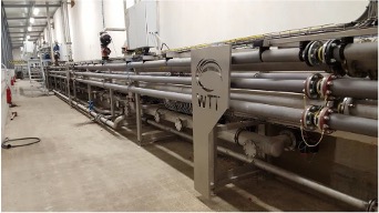
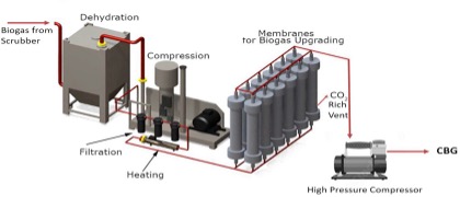
The biogas upgradation technic is based on membrane separation, which can produce Fuel Grade Methane(FGM). The upgradation process starts with purifying the biogas with H2S scrubbers. The purified gas is sent to the membrane upgradation system to produce high quality biogas.
Scrubbing is a common method used to remove hydrogen sulfide from biogas. The process uses the sparger-based gas liquid contact for removal of hydrogen sulphide from the gas. The liquid and rawgas are injected into the scrubber vessel from the bottom. The process is based on the red-ox reaction of chelated polyvalent metal ion, where iron in chelated form in an aqueous medium is used for scrubbing H2S from biogas stream. Iron which exists as both Fe3+ and Fe2+ form, works as acatalyst to scrub the gas of H2S. The gas coming out of the scrubber, which is free of hydrogen sulfide, is then scrubbed with water for cleaning any minute quantities of chemical carried over. The clean gas thus obtained is fit for the end application.
The sulfur component in the hydrogen sulfide is precipitated as elemental sulfur. The scrubbed solution containing sulfur is then taken to the re-generator and regenerated with air using an ejector-based air liquid contact process. The regenerated solution containing sulfur is passed through filter press for sulfur removal. The clear filtrate is then re-cycled back to the scrubber.
Biogas is compressed and fed into modules which contain thousands of porous, hollow fibremembranes. Fast gases permeate the membrane walls while slow gases exit the hollow tube.
This is a passive technology requiring minimal supervision. The system can be scaled by adding or reducing the number of modules online. Multiple stage membrane separation system can produce 99% pure methane. This technology is efficient at removing water vapor and performs for a period of 8 to 12 years.
Biogas upgradation Module is based on Hollow Fibre Membrane Technology to upgrade Biogas to Bio-CNG ensuring the national statutory standards for Auto Fuel, Cooking gas and Gas grid connectivity.
The biogas is a mixture of CO2, methane, and the typical by-products. It is first desulfurized with active carbon, filtered, and pre-dried. The pre-cleaned gas is then drawn in with a compressor, compressed to 12 - 16 bar and upgraded in several membrane stages to give biomethane and a CO2-rich off-gasstream. By judicious combination of membranes, methane of a purity higher than 99% can be obtained. The only equipment needed is a compressor. The methane concentration is obtained in natural gas quality.
Gas separation membranes work on the principle of selective permeation through a membrane surface. The driving force for permeation of the gas through the membrane is the difference betweenthe partial pressures of the gas on the potentate side (the interior of the hollow fibre) and thepermeate side (the exterior of the hollow fibre). The membranes have the highest selectivity and provide a superior technology for processing of crude biogas.
In a separation of Biogas between carbon dioxide and methane, permeation of carbon dioxidethrough the membrane is much faster while methane is retained within. The pre-filtered and de-sulphurised biogas is compressed to 12 - 16 bar pressure for the separation process.
The throughput passes through the cooling process, resulting free condensate is separated from theraw gas, oil filters and coalescing filters for clean gas. The Biogas stream passes through a 2-stageconstructed membrane-gas processing plant and with CH4 separated up to 98% meeting the requirements of vehicular fuel (as per SATAT Scheme and Grid injection norms).
Benefits of membrane separation system:
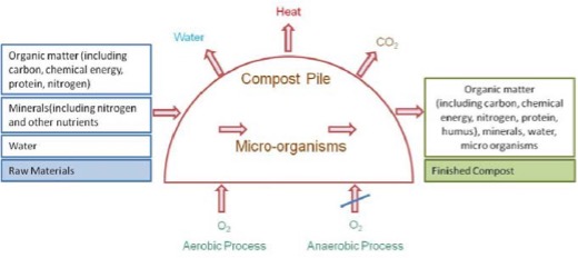
Composting is an organic method of producing compost manure by decomposition and stabilization of organic matter. Composting process is a commonly used method and results in the production of stable compost product reduced in size (when compared to initial size) and free from offensive odours. Compost is particularly useful as organic manure which contains plant nutrients
(nitrogen, phosphorous and potassium) as well as micronutrients which can be utilized for the growth of plants. Composting can be carried out in two ways - aerobically (with the presence of oxygen) or anaerobically (without the presence of oxygen) or vermi-composting or by any other biological mechanism.
Several factors – physical, chemical, and biological influence the process of composting. By controlling some of these influencing factors, natural composting process could be accelerated.These influencing factors also have impact on quality of compost produced. Some of the important physical and chemical factors in the composting process are temperature, C/N ratio, phosphorous, sulphur, moisture, particle size, oxygen flow, etc.
C/N ratio: Optimum C:N ratio is to be maintained for maximizing the compost yield. To bring downthe ratio, sewage and sludge are usually added. Optimum C/N ratio lies between 25-30 : 1.
Phosphorous: One of the essential nutrients for plant growth and determines the quality of compost. Phosphorous concentration might increase as composting proceeds.
Sulphur: Presence of Sulphur in sufficient quantities can lead to the production of volatile, odorous compounds. The major sources of Sulphur are two amino acids (cysteine and methionine). Under well-aerated conditions, the sulfides are oxidized to sulfates, but under anaerobic conditions, they are converted to volatile organic sulfides or to H2S, leading to a bad odour. Some compounds like carbon disulfide, carbonyl sulfide, methyl mercaptan, diethyl sulfide, dimethyl sulfide, and dimethyl disulfide might also lead to bad odours. The site is located away from the human habitation.
Moisture: Optimum moisture content maintained is 50 to 60%. Very high moisture content will result in anaerobic condition. Higher moisture content is essential for mechanical operated system and the waste contains high percentage of fibrous material.
Temperature: Optimum temperature for aerobic composting 65–70 ºC. This temperature results in increased rate of biological activity and faster stabilization of the material and also helps indestruction of pathogens and parasites.
Particle size: Smaller particles produce a homogenous particle size which helps to maintain optimum temperatures. But too fine particles may not allow air to flow into the piles. As observed from the sieve analysis, maximum portion of compostable material falls in the range of 10-20 mm size.
Oxygen and aeration: Aerobic process helps to decompose the organic matter at a faster rate.However, care must be taken not to provide more oxygen which might dry the system and slow down the composting process.
Biologically influencing parameters are microorganisms which breakdown organic matter and producecarbon dioxide, water, heat, and humus. This humus forms the end product as compost. The generalcomposting process consists of four decomposition phases when a suitable environment is provided.
There are various methods of composting and the approach in selecting the appropriate method of composting depends on time required to complete composting. Details like the material and volume to be decomposed, space available, the availability of resources (labour, finances, etc.) and the quality of finished product also need to be considered.
Windrow composting, which is associated with least possible odour issues is generally preferred.Windrow composting is widely used at a large scale as the climatic conditions are semi-arid to arid. Windrow composting is the process of decomposing organic materials to form stabilized organic matter.
It is defined as the controlled, heat dependent, microbiological process of decomposing organic materials into a biologically stable, humus-rich material. Compost is used in agriculture, horticulture, home gardening, land reclamation, wetland mitigation, and erosion prevention to help rebuild soil organic matter and to provide a good medium for plant growth.
Windrow composting process consists of placing pre-processed waste in long narrow piles called windrows that are turned on regular basis for enhancing aeration. These windrows shall haveimpermeable base / platform called compost pad made from concrete of compacted clay of 40 to 50cm thick. The permeability co-efficient should be less than 10-7 cm/sec. This compost pad serves as abarrier to prevent percolation of leachate to sub-soil and groundwater. A slope of 1-2% should alsobe maintained in the base to drain excess water called leachate from the windrows. The base should be circled with a lined drain for collection of leachate or surface runoff. This leachate would be reused for recirculation of nutrients and for maintaining moisture content in windrows. Sufficient space shall be left between windrows for movement of equipment/vehicle used for turning windrow. Windrow composting is basically including the following phases.
This phase starts with transferring the mechanically treated waste to a specific area designedespecially for windrows. A coarse material is spread over that area to enhance ventilation and drainage at the bottom of the windrow pile, and to prevent saturation that might cause anaerobic conditions.
In this phase, the fresh compost produced in the first phase is transferred to another area and piledup and kept to mature for a period of two to four weeks. Unlike phase II there is no turning of the waste and water addition in this phase. Microbial activity takes place at a lower rate in this phase. Matured and dry compost with water content of 25 to 30% is produced.
The matured compost is sieved into fine and coarse fractions using a drum screen. The fine fraction, rich in organic matter, passes through an air density separator to remove sand and grit and is prepared for sale. The coarse fraction is reused in the composting of fresh waste to accelerate the decomposition process.

This technology reader represents a facility with cutting-edge solution for the sustainable treatment of agri waste such as maze, Napier grass, paddy, etc. and other organic waste. This document outlines the technical specifications and operational design of a facility developed for the anaerobic digestion of agri waste and organic waste streams. The plant is designed to receive, process, and convert high-solids agri waste and other organic waste into renewable energy and nutrient-rich fertilizers.
This technology reader represents a facility with cutting-edge solution for the sustainable treatment of agri waste such as maze, Napier grass, paddy, etc. and other organic waste. This document outlines the technical specifications and operational design of a facility developed for the anaerobic digestion of agri waste and organic waste streams. The plant is designed to receive, process, and convert high-solids agri waste and other organic waste into renewable energy and nutrient-rich fertilizers.
Trucked-in feedstocks—including mono-stream agri waste or combination of multi agri waste are collected and stored in dedicated bunkers and tanks. Prior to digestion, all materials are homogenized to ensure consistency.
The pretreatment technology for agricultural residues is a critical factor that directly influences the efficiency of the anaerobic digestion process. Since different types of agri-waste—such as maize stalks, Napier grass, and paddy straw—vary significantly in their fibre content, lignin structure, and moisture levels, the choice of pretreatment must be tailored to each specific biomass type. For example, high-lignin materials like paddy straw may require alkaline or steam explosion pretreatment to break down complex fibres and improve biodegradability, while Napier grass, with its high cellulose and relatively balanced C:N ratio, may only require size reduction and homogenization. Similarly, maize residues might benefit from mechanical shredding and moisture adjustment to facilitate digestion.
Despite these variations in pretreatment needs, we will consistently apply wet anaerobic digestion technology for this application. Wet digestion is particularly suitable for high-moisture feedstocks, which most agricultural wastes become after pretreatment or co-digestion. It offers advantages in substrate handling, microbial activity, and reactor stability, and is compatible with both mesophilic and thermophilic conditions. This approach ensures a robust, scalable, and cost-effective solution for converting agricultural biomass into renewable biogas, while also supporting sustainable waste management and circular economy goals in the agri-sector.
The core of the process is a temperature-controlled anaerobic digestion system that utilizes a two-step approach: pre-digesters initiate organic breakdown, while main digesters focus on methanogenesis to optimize biogas production. The resulting raw biogas is then upgraded via advanced membrane separation into high-quality renewable natural gas (RNG).
Post-digestion, digestate material is separated into solid and liquid fractions. The solid digestate is used as an organic fertilizer. The liquid portion undergoes ammonia stripping, recovering nitrogen in the form of ammonium sulfate—a concentrated and valuable fertilizer product.
This integrated facility demonstrates the future of circular, low-emission energy and nutrient recovery. A detailed video on the process flow can be seen here.
Agricultural residues such as maize stalks, Napier grass, and paddy straw represent abundant and underutilized biomass resources with significant potential for renewable energy generation through anaerobic digestion (AD). These lignocellulosic materials are rich in organic matter—mainly cellulose and hemicellulose—which, under suitable pretreatment and digestion conditions, can yield substantial quantities of biogas.
Utilizing these agri-wastes not only enhances energy security and supports decentralized bioenergy systems, but also helps mitigate open-field burning, reducing air pollution, and contributing to sustainable waste management in the agricultural sector.
The core objective of the facility is to transform organic waste into valuable resources through a controlled anaerobic digestion process. The resulting biogas is upgraded to renewable natural gas (RNG), while the digestate is separated into solid and liquid fractions for further recovery. The solids are utilized as organic fertilizer, and the liquid fraction undergoes ammonia stripping to recover nitrogen in the form of ammonium sulfate.
This facility represents a modern, sustainable approach to managing agri waste while supporting circular economy goals. It incorporates robust feedstock handling systems, advanced mixing technologies, grit management strategies, and downstream biogas purification and nutrient recovery processes. The following sections describe each system component in detail, highlighting their function, capacity, and integration within the overall process flow.
This section outlines the procedures and systems for receiving, handling, storing, and preparing feedstocks prior to anaerobic digestion. The primary solid feedstock, agri waste is collected from farms. All feedstocks are processed and homogenized to ensure consistent slurry quality for optimal digester performance. Supporting systems include water addition, recycled liquid integration, and storage infrastructure designed for operational efficiency and emissions control.
The choice of pretreatment technology depends on the type of agricultural waste—such as maize stalks, Napier grass, or paddy straw—since each has different fiber content and biodegradability. High-lignin residues like paddy straw may need chemical or steam-based pretreatment, while others may only require shredding or moisture adjustment. Regardless of the feedstock, we will adopt wet anaerobic digestion technology, which is well-suited for high-moisture biomass, ensures efficient biogas production, and supports a scalable and sustainable waste-to-energy solution.
The pretreated waste is received into underground bins and peristaltic pumps forward the waste to a distribution conveyor into the storage bunkers. The bunkers can get wetted to form a crust over the waste to reduce ammonia emissions into the air. From the bunkers, the waste is moved by skid steer as needed, to smaller underground bins where a screw conveyor picks up the waste and feeds peristaltic pumps, to pump the waste into the mixing tanks. Water is added to the waste with spray nozzles in the conveyor compartment to increase the efficiency of pumping the waste / water slurry to the mixing tanks.The mixers in tank stir the slurry mixture to ensure a homogenous slurry mixture for feeding the digesters.
Grit present in the waste can either be kept in suspension and allowed to pass through the anaerobic digestion process—where it would be removed along with the digestate solids post-digestion—or it may be removed earlier, either at the time of waste reception or after storage and before being fed to the digesters. Each option presents its own set of advantages, disadvantages, and cost implications, all of which must be carefully evaluated. The currently preferred approach is to remove grit using settling tanks and screens after digestion and prior to the separation of digestate solids.
The agri waste is received by way of 20 – 25 ton back dump trucks 5 days a week 8 hours of each 9-hour shift. The receiving area will accommodate two trucks at a time and each truck will be unloaded within 20 – 25 minutes allowing for receiving three to four trucks per hour.
The waste will be received into two underground bins with motor-controlled covers, each with a capacity of 40 tons. The truck will back up a ground level hopper chute and activate the motor control to open the bin cover. Once the cover is open, the truck will back-dump its load into the hopper chute, which directs the waste into the below-ground bin. After the truck is emptied, the driver will activate the closing of the bin cover and, once closed, will pull away to make room for the next truck.
The agri waste will be unloaded into separate underground bins sized with a capacity of 40 tons.The average truck load will be about 20 to 25 tons but will vary between 15 and 27 tons in each load with a total of 15 -16 trucks per day required to deliver all the waste.
The bins are equipped with water spray nozzles to allow moisturizing each load of waste with about 10 tons of water per load.The bottom of the bin is equipped with a screw conveyor that will move the mixture to the suction side of peristaltic pump which will pump the waste to a distribution conveyor system above the storage bunkers.
Storage of the waste in the bunkers sized for 14 days of storage of each type of waste. Each bunker can hold about 884 m3 of waste, a total of 10 bunkers will be constructed.
The bunkers will be covered with a building structure that has natural ventilation. The bunkers will have water sprayers to wet the waste with fresh water to crust the top of the storage pile and prevent excess ammonia vapors escaping into the atmosphere.
The bunkers will be filled from the bins using a distribution conveyor in each bunker, to allow for even distribution of waste within the bunker.
The waste bunkers will be unloaded with a bucket loader with the waste dropped into the hatch of a covered underground bin with a capacity of 11.3 m3 each, two bins total. Each bin will be equipped with a screw conveyor and water spray nozzles with water added as the waste is conveyed to a peristaltic pump. The waste and water slurry mix will be pumped to the mixing tanks.
There will be two mixing tanks sized for one day capacity to achieve a homogenous mix of the feedstocks.
Mixing of the slurry in the tanks will be accomplished with external pumps recirculating the slurry mix with the suction of the pumps drawing from the bottom of the tank and returned through several piped connections along the outside of tanks creating a continuous horizontal and vertical stirring action of the mixture in the tanks.
The two mix tanks combine have a capacity for one day of storage plus 5% additional unfilled headspace, approximately 1 million liters each. The feedstock slurry will be pumped to the AD Hydrolysis Tanks using three pumps total each sized at 50% of the total pumping required, approximate flow rate of 742 lpm for each pump.
The anaerobic digestion facility is designed to process a feed slurry with a daily input capacity of approximately 2,005.75 tons per day (tpd), equivalent to 1,823.4 metric tons per day (mtpd). This corresponds to a total volume of 2,032.4 cubic meters of slurry handled each day. The feed slurry is characterized by a dry matter/total solids (DM/TS) content of 16.86%, indicating a relatively high solids concentration suitable for high-solids digestion processes. The total nitrogen content of the feedstock is approximately 0.42% of the dry matter, which provides a balanced nutrient profile conducive to stable anaerobic digestion and efficient biogas production. These parameters define the input requirements necessary to maintain optimal operational performance of the biogas plant.
Hydrolysis is the first step in the anaerobic digestion of organic material. There are two hydrolysis tanks each sized for 5 days of HRT. Each tank is approximately 1,342,260 gallons (5081 m3) plus head space. The temperature of the feed slurry in the anaerobic digesters shall be maintained in the thermophilic temperature range of 122 - 131⁰F (50 to 55⁰C).Total HRT for thermophilic anaerobic digestion is 20 days including hydrolysis.
Each hydrolysis tank will supply feedstock slurry to two digesters. Each of the digesters is sized for 15 days HRT, approximately 7,621.5 m3 each plus head space. The feedstock slurry in the digesters will be continuously stirred by way of a recirculation loop drawing from the top of the digester tank, heated to a temperature of at least 52⁰C (125.5⁰F) with an external heat exchanger and returned to the digester near the bottom of the tank.
Each digester is equipped with four recirculation loops with an estimated flow rate of approximately 1,500 m3/hour such that a total flow into and from the digester and heat exchangers is 6,000 m3/hour.
Temperature control of the digester slurry is provided by an external heat exchanger loop and gas fired hot water boiler supplied with the digester auxiliary equipment.
The hydrolysis tanks will have a positive suction ventilation system to draw out any biogas produced and will be piped to a common header with the AD tanks.
Each anaerobic digester shall be equipped with a double membrane roof and support structure that collects the biogas. The biogas outlet from the membrane roof of each digester is piped to a common header that includes the hydrolysis tanks vent lines. Two biogas blowers operating as part of the biogas treatment and upgrade system will maintain a low suction pressure drawing the biogas from the membrane roofs at a rate consistent with the amount produced.
Digester effluent (digestate) from the digesters using a common header pipe from the 4 digesters with two 100% sized pumps (alternating as needed) at a rate of approximately 66.25 m3/hour is pumped to the digestate buffer tank.
The digestate buffer tank will be a conical bottom tank used to settle grit to a screw conveyor for removal. The buffer tank provides for a continuous flow without upset to the digestate solids removal system and allows for any biogas trapped in the effluent time to percolate to the top of the buffer tank and be drawn out by a biogas blower to the biogas treatment system with the biogas collected from the digesters.
The digestate buffer tank shall is sized for a retention time of 30 minutes to allow grit to settle while the undigested solids and liquid is pumped to the digestate solids separation system by three pumps each sized at 50% flow.
The separated grit is processed through a screen that allows the water to be recycled while the grit is combined with the separated solids at the digestate solids cake dryer.
The digestate will be dewatered utilizing three decanter centrifuges operating in parallel at a rate of 22.1 m3/hour each. The solids will be dewatered to approximately 70% moisture. Polymers may be required to achieve separated solids of 70% moisture or less.
The solids from each centrifuge will be collected into a hopper and then transferred to a feed hopper for a rotary drum dryer by way of a screw conveyor. The hoppers and screw conveyor should be sized to handle 110 tons per day (100 metric tons per day) dry basis of solids transfer.
The liquid fraction (centrate) will be stored in a buffer tank sized to hold the total flow for at least for a 6-hour period (one quarter of the total flow for 1 day). The expected total liquid fraction flow rate is approximately 1343 m3/day. The buffer tank will be sized for at least 340.6 m3.
The digestate solids received at 35% dry matter and 65% moisture will be dried to 50% dry matter and 50% moisture using solar radiant heat. The digestate solid will be spread in layers in open drying rows and turned weekly to promote drying. When dried to 85% dry matter, the digestate solids will be collected by skid steer and loaded into a hopper for bulk loading or to a pelletizer that will compress and pelletize the digestate solids.
The raw biogas from the anaerobic digesters will be saturated with moisture and contain particulate matter, methane (CH4), carbon dioxide (CO2), hydrogen sulfide (H2S), oxygen (O2) and trace amounts of inert gases and volatile organic compounds (VOCs). The biogas treatment system is designed to remove moisture, particulate matter and H2S.
The expected total flow rate is approximately 100,487 m3/day. The biogas treatment system consists of two complete systems operating in parallel with a capability to clean 42.47 m3/min each, 84.95 m3/min of biogas total.
Each system will be designed such that media changes can be accomplished while the system is in operation. This will require lead-lag vessels. Media vessels may be shared between trains, for example the offline lag vessels can be valved as the lead vessels for either train as can each of the lead vessels when they become the lag vessel after a media changeout.
The cleaned biogas will be upgraded to pipeline quality renewable natural gas (RNG) with a membrane separation system that allows separation of the CO2 and the CH4.
The system shall be designed for a flow rate of approximately 55,560 m3/day and have an efficiency of at least 97.5% recovery of the biomethane with an option of 99% recovery.
The CO2 stream shall be recovered and chilled until it is in a liquid state to be stored for transport. An estimated 50,970 to 56,633 m3/day of CO2 should be recovered and processed into approximately 92 – 102 tons/day of liquid CO2.
The biogas to be treated approximates the parameters in the first table below and the final values will be determined by the design of the AD system and mass balance information.
The second table gives the parameters of Treated Biogas for Pipeline Injection.
The liquid fraction from the digestate solids decanter stored in a buffer tank will be processed by minimum of four stripping systems (streets), each system to consist of 3 ammonia strippers and 1 CO2 stripper, total of atleast 12 ammonia strippers and 4 CO2 strippers. In each stripper air and liquid fraction are brought in close contact with each other. The liquid fraction is sprayed in at the top of each stripper using full-cone spray nozzles to maximize the contact area between liquid and gas.
The spray nozzles will be selected to optimize droplet size, but still sufficiently large to avoid blockage. As such mass transfer area between liquid and gas will be maximized for fouling conditions. Air is introduced into each at the bottom via an air distribution system. The applied air flow rates will provide sufficient turbulence to maximize mass transfer in the system. Each stripper will be equipped with two pumps. One pump will provide internal circulation for spraying, while the other is used to feed the next stripper.
The goal of this stripper is to remove CO2 from liquid fraction, thereby increasing its pH, avoiding the need for caustic soda (NaOH) dosing every day. Fresh air is used as the stripping gas. The CO2 stripping is performed without additional heating since CO2 is more volatile than NH3. As such mostly CO2 is stripped. The CO2stripper off-air is mixed up with the NH3 laden air from the NH3 strippers. The air mixture subsequently goes to the acid scrubber section for NH3 recovery.
Each street of CO2 strippers shall be capable of processing approximately 289 tpd (262.7 mtpd).
To strip ammonia, the liquid fraction will be heated to a temperature of 65°C (149°F). Each street will have heat exchangers on the feed to the first NH3 stripper to provide the required heat. 3 NH3 strippers are in place in each street. Liquid fraction will go through the system front to back, while air goes back to front. In each stripper the liquid fraction is contacted with air to maximize NH3 transfer from liquid to gas. This results in an NH3 laden air stream, and a liquid fraction stripped from NH3. The NH3 laden air stream is led to the scrubber section for NH3 recovery as ammonium sulfate, (NH4)2SO4. Scrubbed air is subsequently reused for stripping.
The influent ammonium concentration is around 3,526 mg N/L and the effluent concentration after stripping is 1,200 mg N/L. This means that 66% of the dissolved ammonium will be removed and recovered as (NH4)2SO4.
Each street includes a scrubber section for NH3 recovery. The gas stream resulting from combining the CO2stripper exhaust and NH3 stripping exhaust is fed to the main scrubber, where the bulk of the NH3 is absorbed into the liquid acid phase. 70% w/w sulfuric acid (H2SO4) is used to maintain acid conditions. The exhaust gas of the main scrubber is then split. The main fraction is recycled to the NH3 strippers. The rest is purged through a small acid scrubber to prevent CO2 accumulation in the air recycle. The small scrubber is operated at low pH (<3) to minimize NH3 concentration in the purged air. The effluent ammonia concentration of the recirculated air is expected to be around 500 ppm. Purged air NH3 concentration remains below 15ppm.
Ammonia rich air is introduced at the bottom of the scrubber column while the sulfuric acid solution is sprayed at the top, creating a counter-current flow between the liquid and air. In addition, the scrubber is filled with packing material to optimize the contact area between liquid and water. In the scrubber an ammonium sulfate fertilizer is created, (NH4)2SO4. Water is added to the scrubber to obtain the desired fertilizer concentration (35% w/w) and compensate for volume losses due to evaporation. This is necessary to avoid ammonium sulphate crystallization in the scrubbers: above 35% w/w (NH4)2SO4 the probability of crystallization considerably increases potentially resulting in process disruption.
The system uses approximately 27.7 tpd (25.2 mtpd) of water and 13.4 tpd (12.2 mtpd) of acid to produce 36.2 tpd (32.9 mtpd) of fertilizer with 35% (NH4)SO4 and recover 3.7 tpd (2.44 mtpd) of ammonia nitrogen.
To mitigate risks and secure investor returns in the renewable energy project, SusBDe provides a comprehensive set of guarantees structured around three key areas:
The insurance program and financial performance guarantee structures are designed to be transferable directly to investors, further enhancing financial security and investor confidence.